The cattle licking salt block machine processes the nutrients needed by cattle and sheep into a block feed for cattle and sheep to lick. Licking bricks have different shapes, cylindrical and square. Most of the licking bricks have a hole in the middle for fixing. The licking brick made by the salt licking machine through high pressure is high in density and hardness, which can adapt to various extreme weather conditions. The licking brick that is concentrated by high pressure can greatly reduce waste.
The automatic livestock salt licking brick machine adopts a four-column and three-beam hydraulic press with a professional mold base (or a four-column and four-beam hydraulic press). The equipment has a compact structure, a high degree of automation, a low failure rate, and high work efficiency. Not only the pressure is high, but also the two-way floating pressure is applied. The extruded product is not only high in density but also consistent in density from top to bottom. The three positions of loading, forming, and demoulding have mechanical block positioning and stepless adjustment mechanism, which confirms the stable and adjustable geometric dimensions of the product, so as to ensure that the weight of the salt licking brick is consistent.

Working Principle of cattle licking salt block machine
Mix the materials and add them to the upper hopper after the equipment. The materials in the hopper are added to the feeding frame in a quantitative manner.
The feeding cylinder drives the feeding frame forward, adding the material into the mold, and then the feeding cylinder returns to its position.
The sub-cylinder drives the piston rod and punch of the main cylinder to press down quickly. When the punch enters the mold cavity, the sub-cylinder turns into the main cylinder to slowly pressurize, and the materials in the mold are pressed into high-density bricks by high pressure (de-molding) The floating cylinder descends at the same time to realize two-way floating suppression).
The main cylinder rises slightly (the punch does not come out of the mold), and the demolding floating cylinder drives the mold frame to fall and pull the licking bricks out of the mold.
The core cylinder pulls out the core rod, the sub-cylinder and the main cylinder rise, and the feeding cylinder advances to push out the finished product while the feeding frame moves to the top of the mold.
The demolding cylinder drives the mold frame to rise to form a cavity to complete the feeding and enter the next cycle program.

Features of livestock salt licking brick machine
Our company is a professional manufacturer of cattle licking salt block machine. According to user needs, four-column and three-beam hydraulic press with professional mold base or four-column and four-beam hydraulic press can be adopted, which is flexible and can meet the needs of different users. The equipment has a compact structure, a high degree of automation, and a failure rate. Low and high work efficiency.
The hydraulic pump station has a reasonable structure design, adopts a large flow cartridge valve block and a unique oil circuit design to make the hydraulic system work stably with low heat generation, effectively realizing continuous production. Cooling users can choose cooling pools, cooling towers, refrigerators, etc. according to their needs. Our company’s pumping stations are equipped with coolers, which can be seamlessly connected.

The brick licking machine of our company uses stainless steel in contact with the material, which not only prevents the material from corroding the equipment but also makes the pressed brick licking a higher grade.
The equipment adopts two-way floating pressure, and the extruded products are not only high in density, but also consistent in the upper and lower densities; the positioning of the guide post has high accuracy, and the mechanical stop positioning and stepless adjustment mechanism of the three positions of loading, forming and demolding ensure Improved the dimensional stability of the salt bricks. The hole of the licking brick adopts a core-pulling cylinder to ensure the size and appearance of the hole.
Our company’s mold is made of Cr12MoV, which is finished by vacuum quenching, which is not only wear-resistant but also not easy to rust.
Cattle licking salt block machine specifications
| Item | Unit | HX400 | HX500 | HX720 | |
| Nominal force | kN | 4000 | 5000 | 7200 | |
| Maximum working pressure of the liquid | Mpa | 25 | 25 | 25 | |
| The maximum distance between the lower plane of the slider and the worktable | mm | 1200 | 1200 | 1200 | |
| Slider travel parameters | Suppressing force | kN | 4000 | 5000 | 7200 |
| Return force | kN | 55 | 55 | 115 | |
| journey | mm | 450 | 500 | 500 | |
| Fast down speed | mm/s | 130 | 120 | 110 | |
| Slow down | mm/s | 18 | 15 | 14 | |
| Floating suppression speed | mm/s | 8 | 8 | 8 | |
| Return speed | mm/s | 85 | 80 | 70 | |
| Operating parameters of ejector piston (optional) | Ejection force | kN | 950 | 1150 | 1560 |
| Pull downforce | kN | 260 | 300 | 500 | |
| journey | mm | 300 | 300 | 300 | |
| Jacking speed | mm/s | 95 | 90 | 80 | |
| Floating downward speed | mm/s | 8 | 8 | 8 | |
| Retraction speed | mm/s | 80 | 75 | 70 | |
| Lower center cylinder piston parameters | Reach out | kN | 80 | 80 | 120 |
| Retraction force | kN | 50 | 50 | 50 | |
| journey | mm | 300 | 300 | 300 | |
| Effective area of the worktable | mm | 700×750 | 775×850 | 900×1050 | |
| Total motor power | kw | 30 | 30 | 45 | |
| Briquette weight | Kg | 2-8 | 5-10 | 10-20 (or 2 pieces at a time of 5 kg) | |
| You can press 3 times per minute | Press 2.5 times per minute | ||||
| Only 1 piece can be pressed at a time, 2 pieces can be produced for those below 2KG | 2 pieces can be pressed under 5 kg each time |
Size options
5 kg (square 145, height 130; circle 155, H148)
10 kg (square 185, height 175)
4 kg of soft water salt (length 280, width 88, height 90)
2 kg of soft water salt (length 140, Width 88, height 90)
20 kg (square 240, height 185)

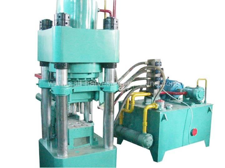
Cattle salt licking block machine structure
The host is composed of the upper, middle, and lower beams, hydraulic main cylinder assembly, jacking floating cylinder, core pulling cylinder, feeding cylinder, rear feeding belt, high-precision mold base and mold, liquid filling system, etc.
The upper, middle, and lower beams are connected by columns and nuts. The front end of the main hydraulic cylinder is flanged to the bottom of the beam, the cylinder piston rod is connected to the middle beam, and the upper punch is connected to the lower part of the middle beam. The high-precision mold base is installed on the lower beam, consisting of four guide pillars and two guide pillars, lifting floating cylinders, lower beams, and the middle beam are connected to form a high-precision pressing structure. The mold is fixed on the upper mold base of the high-precision mold base. On the board, the lower punch is fixed on the lower middle board of the high-precision mold base. The punch is directly connected to the top end. Both die sleeve and punch can be disassembled and replaced.
The rear feeding belt is fixed behind the upper beam of the equipment, and the materials are stored in the hopper above the feeding belt. The equipment program controls the feeding hopper at the bottom to form the feeding system of the equipment.
The liquid filling system is located on the side of the upper beam to supplement the oil required for the rapid advance of the main cylinder.
The composition of the hydraulic system
The hydraulic system of this equipment is composed of an oil tank, motor, oil pump, cartridge valve, pressure gauge, level gauge, high-pressure hose, thermometer, oil return filter, cooler, etc.
The oil enters the hydraulic cylinder through the oil pump, pipeline, and hydraulic components, and the hydraulic components control the movement of the cylinder. Realize actions such as squeezing and returning the pie. The system pressure is adjusted by the overflow valve, and the automatic mechanical action is controlled by the PLC and runs automatically. After the finished product is compacted, the pressure relay sends a signal and then executes the next action.
The oil temperature in the oil tank is adjusted by a cooler. When the oil temperature is too high, increase the water volume and circulation speed to force cooling; otherwise, reduce the water volume and circulation speed.
Electrical system overview
This system uses AC, 380V, 50HZ power supply, control power supply 220V, PLC uses 24V, according to the process needs, it can be divided into “manual adjustment”, “stepping” and “automatic” three methods to complete the machining process. The control system adopts PLC. The programming controller is equipped with a man-machine interface for adjusting the fine process time. The working program has been adjusted before leaving the factory and stored in the PLC. It is not easy for the user to change it casually. Some small process times can be adjusted by referring to the display.

Cattle licking salt block machine debugging
For the foundation of the equipment, the supplier shall provide drawings, and the buyer shall be responsible for the specific construction.
After the product is assembled in the supplier’s factory, the buyer shall be notified in time of the specific delivery time and preparation work required for installation.
The supplier is responsible for the installation and commissioning of the equipment on the demand side, and the demander cooperates and provides the lifting equipment, water, electricity, and necessary conditions required for the installation.
In the process of equipment installation and commissioning on the demand side, the supplier will provide free training and technical consultation services to relevant technical personnel of the demand side.
After installation and commissioning, both parties shall jointly check and accept according to the signed contract.
The company is responsible for debugging and guiding the installation of the equipment, and the user assigns personnel to cooperate. Provide the necessary lifting tools.
Service of livestock salt licking brick machine
During the warranty period, all services caused by non-human and irresistible forces are free (except for vulnerable parts); after the warranty period, maintenance services will be charged for the cost.
After the quality assurance period, the repair and maintenance are combined with telephone consultation and on-site repair service (paid), and long-term supply of spare parts.
Respond within 1 hour after receiving the user’s notice, and rush to the user for after-sales service within 24 hours within the province (within 48 hours outside the province).
Installation of food, lodging, and transportation abroad.